


Isometric Drawings: Visualizing and Validating Piping Systems
Isometric drawings, a specialised form of technical drawing, play a crucial role in the design, construction, and maintenance of piping systems. These drawings provide a three-dimensional representation of a piping system, aiding in understanding its layout, components, and connections. In this blog post, we will explore the significance of isometric drawings in the context of piping systems and delve into the key benefits they offer.
[edit] Understanding Isometric Drawings
An isometric drawing is a type of axonometric projection where the three axes (x, y, and z) are equally inclined to the viewing plane. This results in a perspective that is both realistic and easy to interpret. In piping systems, isometric drawings are particularly valuable because they allow engineers and technicians to:
- Visualise the Piping Layout: Isometric drawings provide a clear and comprehensive view of the piping system's layout, including the arrangement of pipes, fittings, valves, and other components. This helps in understanding the flow path and identifying potential conflicts or obstructions.
- Validate Design Accuracy: By comparing isometric drawings with actual site conditions or construction plans, engineers can verify the accuracy of the design. This helps to prevent errors and costly rework during the construction phase.
- Communicate Effectively: Isometric drawings serve as a common language for all stakeholders involved in a piping project. They provide a visual representation that can be easily understood by engineers, technicians, contractors, and inspectors.
- Identify Piping Components: Isometric drawings clearly label the various components of the piping system, such as pipes, valves, fittings, and supports. This helps in ordering the correct materials and ensuring proper installation.
- Plan Installation and Maintenance: Isometric drawings can be used to plan the installation sequence and identify potential challenges. They also aid in developing maintenance schedules and procedures.
[edit] Key Benefits of Isometric Drawings
The use of isometric drawings in piping systems offers several significant benefits, including:
- Improved Efficiency: Isometric drawings streamline the design, construction, and maintenance processes by providing a clear and concise representation of the piping system. This reduces the likelihood of errors and delays.
- Cost Reduction: By identifying potential issues early in the design phase, isometric drawings can help to avoid costly mistakes during construction. They also facilitate efficient installation and maintenance, reducing downtime and operational expenses.
- Enhanced Safety: Isometric drawings contribute to a safer working environment by providing a clear understanding of the piping system's layout and potential hazards. This helps to prevent accidents and injuries.
- Improved Quality: The use of isometric drawings ensures that the piping system is constructed according to the design specifications, leading to a higher quality product.
In conclusion, isometric drawings are an essential tool for visualising and validating piping systems. They provide a valuable resource for engineers, technicians, and contractors, facilitating effective communication, design accuracy, and efficient project execution. By leveraging the power of isometric drawings, organisations can improve the quality, safety, and cost-effectiveness of their piping projects.
[edit] Related articles on Designing Buildings
- Asset information requirements AIR.
- Blockchain in the built environment.
- BIM articles.
- BIM dimensions.
- BIM execution plan.
- BIM glossary of terms.
- BIM level 2.
- BIM maturity levels.
- BIM resources.
- Building drawing software.
- Construction Operations Building Information Exchange (COBie).
- Common data environment.
- Data drops..
- Digital information.
- Digital model.
- Geographic information system GIS.
- Geographic Information Systems: QGIS.
- Geospatial.
- Global positioning systems and global navigation satellite systems.
- Government Soft Landings.
- Information manager.
- Level of detail.
- MEP BIM and the building lifecycle.
- Revit.
- Soft landings.
- Types of drawings.
- Value engineering in building design and construction.
Featured articles and news
ECA progress on Welsh Recharging Electrical Skills Charter
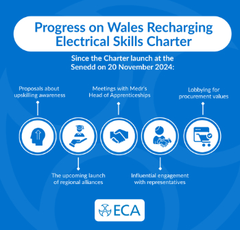
Working hard to make progress on the ‘asks’ of the Recharging Electrical Skills Charter at the Senedd in Wales.
A brief history from 1890s to 2020s.
CIOB and CORBON combine forces

To elevate professional standards in Nigeria’s construction industry.
Amendment to the GB Energy Bill welcomed by ECA

Move prevents nationally-owned energy company from investing in solar panels produced by modern slavery.

Gregor Harvie argues that AI is state-sanctioned theft of IP.

Heat pumps, vehicle chargers and heating appliances must be sold with smart functionality.
Experimental AI housing target help for councils

Experimental AI could help councils meet housing targets by digitising records.
New-style degrees set for reformed ARB accreditation
Following the ARB Tomorrow's Architects competency outcomes for Architects.
BSRIA Occupant Wellbeing survey BOW
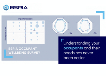
Occupant satisfaction and wellbeing tool inc. physical environment, indoor facilities, functionality and accessibility.

Preserving, waterproofing and decorating buildings.

Many resources for visitors aswell as new features for members.
Using technology to empower communities

The Community data platform; capturing the DNA of a place and fostering participation, for better design.
Heat pump and wind turbine sound calculations for PDRs

MCS publish updated sound calculation standards for permitted development installations.
Homes England creates largest housing-led site in the North
Successful, 34 hectare land acquisition with the residential allocation now completed.
Scottish apprenticeship training proposals

General support although better accountability and transparency is sought.
The history of building regulations

A story of belated action in response to crisis.
Moisture, fire safety and emerging trends in living walls

How wet is your wall?

Current policy explained and newly published consultation by the UK and Welsh Governments.
British architecture 1919–39. Book review.

Conservation of listed prefabs in Moseley.
Energy industry calls for urgent reform.